Waveguide Couplers
Directional Coupler
-
class
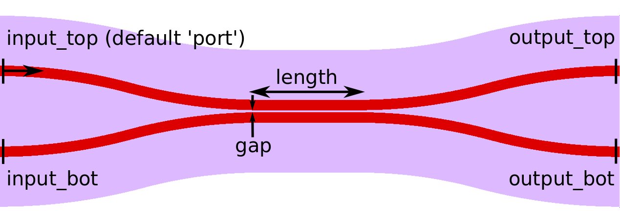
picwriter.components.DirectionalCoupler(wgt, length, gap, angle=0.5235987755982988, parity=1, port=(0, 0), direction=u'EAST')¶ Directional Coupler Cell class.
- Args:
- wgt (WaveguideTemplate): WaveguideTemplate object
- length (float): Length of the coupling region.
- gap (float): Distance between the two waveguides.
- Keyword Args:
- angle (float): Angle in radians (between 0 and pi/2) at which the waveguide bends towards the coupling region. Default=pi/6.
- parity (integer -1 or 1): If -1, mirror-flips the structure so that the input port is actually the bottom port. Default = 1.
- port (tuple): Cartesian coordinate of the input port (AT TOP if parity=1, AT BOTTOM if parity=-1). Defaults to (0,0).
- direction (string): Direction that the component will point towards, can be of type ‘NORTH’, ‘WEST’, ‘SOUTH’, ‘EAST’, OR an angle (float, in radians). Defaults to ‘EAST’.
- Members:
- portlist (dict): Dictionary with the relevant port information
- Portlist format:
- portlist[‘input_top’] = {‘port’: (x1,y1), ‘direction’: ‘dir1’}
- portlist[‘input_bot’] = {‘port’: (x2,y2), ‘direction’: ‘dir1’}
- portlist[‘output_top’] = {‘port’: (x3, y3), ‘direction’: ‘dir3’}
- portlist[‘output_bot’] = {‘port’: (x4, y4), ‘direction’: ‘dir4’}
Where in the above (x1,y1) (or (x2,y2) if parity=-1) is the same as the input ‘port’, (x3, y3), and (x4, y4) are the two output port locations. Directions ‘dir1’, ‘dir2’, etc. are of type ‘NORTH’, ‘WEST’, ‘SOUTH’, ‘EAST’, or an angle in radians. ‘Direction’ points towards the waveguide that will connect to it.
Adiabatic 3dB Coupler
-
class
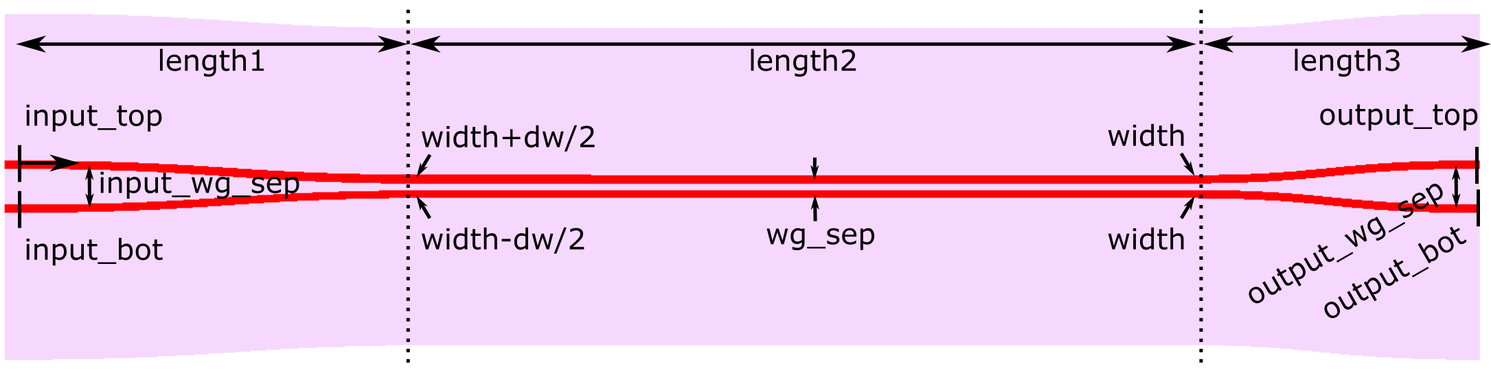
picwriter.components.AdiabaticCoupler(wgt, length1, length2, length3, wg_sep, input_wg_sep, output_wg_sep, dw, port=(0, 0), direction=u'EAST')¶ Adiabatic Coupler Cell class. Design based on asymmetric adiabatic 3dB coupler designs, such as those from https://doi.org/10.1364/CLEO.2010.CThAA2, https://doi.org/10.1364/CLEO_SI.2017.SF1I.5, and https://doi.org/10.1364/CLEO_SI.2018.STh4B.4. Uses Bezier curves for the input, with poles set to half of the x-length of the S-bend.
In this design, Region I is the first half of the input S-bend waveguide where the input waveguides widths taper by +dw and -dw, Region II is the second half of the S-bend waveguide with constant, unbalanced widths, Region III is the region where the two asymmetric waveguides gradually come together, Region IV is the coupling region where the waveguides taper back to the original width at a fixed distance from one another, and Region IV is the output S-bend waveguide.
- Args:
- wgt (WaveguideTemplate): WaveguideTemplate object
- length1 (float): Length of the region that gradually brings the two assymetric waveguides together. In this region the waveguide widths gradually change to be different by dw.
- length2 (float): Length of the coupling region, where the asymmetric waveguides gradually become the same width.
- length3 (float): Length of the output region where the two waveguides separate.
- wg_sep (float): Distance between the two waveguides, center-to-center, in the coupling region (Region 2).
- input_wg_sep (float): Separation of the two waveguides at the input, center-to-center.
- output_wg_sep (float): Separation of the two waveguides at the output, center-to-center.
- dw (float): Change in waveguide width. In Region 1, the top arm tapers to the waveguide width+dw/2.0, bottom taper to width-dw/2.0.
- Keyword Args:
- port (tuple): Cartesian coordinate of the input port (top left). Defaults to (0,0).
- direction (string): Direction that the component will point towards, can be of type ‘NORTH’, ‘WEST’, ‘SOUTH’, ‘EAST’, OR an angle (float, in radians). Defaults to ‘EAST’.
- Members:
- portlist (dict): Dictionary with the relevant port information
- Portlist format:
- portlist[‘input_top’] = {‘port’: (x1,y1), ‘direction’: ‘dir1’}
- portlist[‘input_bot’] = {‘port’: (x2,y2), ‘direction’: ‘dir1’}
- portlist[‘output_top’] = {‘port’: (x3, y3), ‘direction’: ‘dir3’}
- portlist[‘output_bot’] = {‘port’: (x4, y4), ‘direction’: ‘dir4’}
Where in the above (x1,y1) is the same as the input ‘port’, (x3, y3), and (x4, y4) are the two output port locations. Directions ‘dir1’, ‘dir2’, etc. are of type ‘NORTH’, ‘WEST’, ‘SOUTH’, ‘EAST’, or an angle in radians. ‘Direction’ points towards the waveguide that will connect to it.
Adiabatic Full Coupler
-
class
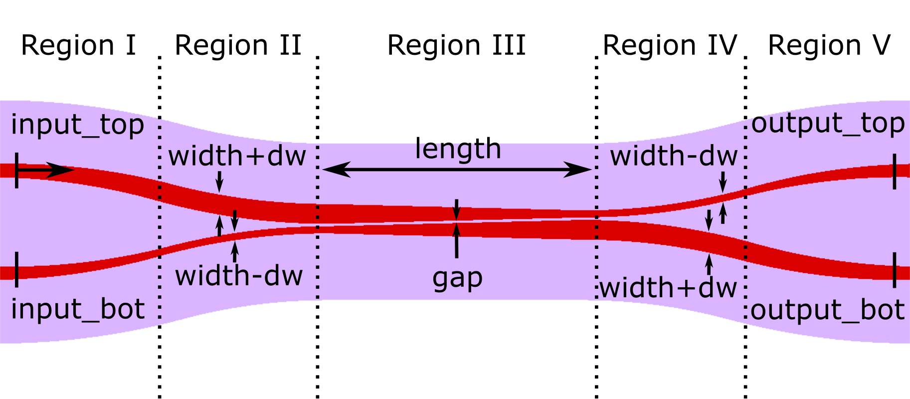
picwriter.components.FullCoupler(wgt, length, gap, dw, angle=0.5235987755982988, parity=1, port=(0, 0), direction=u'EAST')¶ Adiabatic Full Cell class. Design based on asymmetric adiabatic full coupler designs, such as the one reported in ‘Integrated Optic Adiabatic Devices on Silicon’ by Y. Shani, et al (IEEE Journal of Quantum Electronics, Vol. 27, No. 3 March 1991).
In this design, Region I is the first half of the input S-bend waveguide where the input waveguides widths taper by +dw and -dw, Region II is the second half of the S-bend waveguide with constant, unbalanced widths, Region III is the coupling region where the waveguides from unbalanced widths to balanced widths to reverse polarity unbalanced widths, Region IV is the fixed width waveguide that curves away from the coupling region, and Region V is the final curve where the waveguides taper back to the regular width specified in the waveguide template.
- Args:
- wgt (WaveguideTemplate): WaveguideTemplate object
- length (float): Length of the coupling region.
- gap (float): Distance between the two waveguides.
- dw (float): Change in waveguide width. Top arm tapers to the waveguide width - dw, bottom taper to width - dw.
- Keyword Args:
- angle (float): Angle in radians (between 0 and pi/2) at which the waveguide bends towards the coupling region. Default=pi/6.
- parity (integer -1 or 1): If -1, mirror-flips the structure so that the input port is actually the bottom port. Default = 1.
- port (tuple): Cartesian coordinate of the input port (AT TOP if parity=1, AT BOTTOM if parity=-1). Defaults to (0,0).
- direction (string): Direction that the component will point towards, can be of type ‘NORTH’, ‘WEST’, ‘SOUTH’, ‘EAST’, OR an angle (float, in radians). Defaults to ‘EAST’.
- Members:
- portlist (dict): Dictionary with the relevant port information
- Portlist format:
- portlist[‘input_top’] = {‘port’: (x1,y1), ‘direction’: ‘dir1’}
- portlist[‘input_bot’] = {‘port’: (x2,y2), ‘direction’: ‘dir1’}
- portlist[‘output_top’] = {‘port’: (x3, y3), ‘direction’: ‘dir3’}
- portlist[‘output_bot’] = {‘port’: (x4, y4), ‘direction’: ‘dir4’}
Where in the above (x1,y1) (or (x2,y2) if parity=-1) is the same as the input ‘port’, (x3, y3), and (x4, y4) are the two output port locations. Directions ‘dir1’, ‘dir2’, etc. are of type ‘NORTH’, ‘WEST’, ‘SOUTH’, ‘EAST’, or an angle in radians. ‘Direction’ points towards the waveguide that will connect to it.
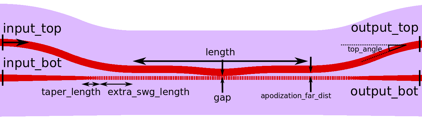
Sub-wavelength Grating Assisted Contra-Directional Coupler
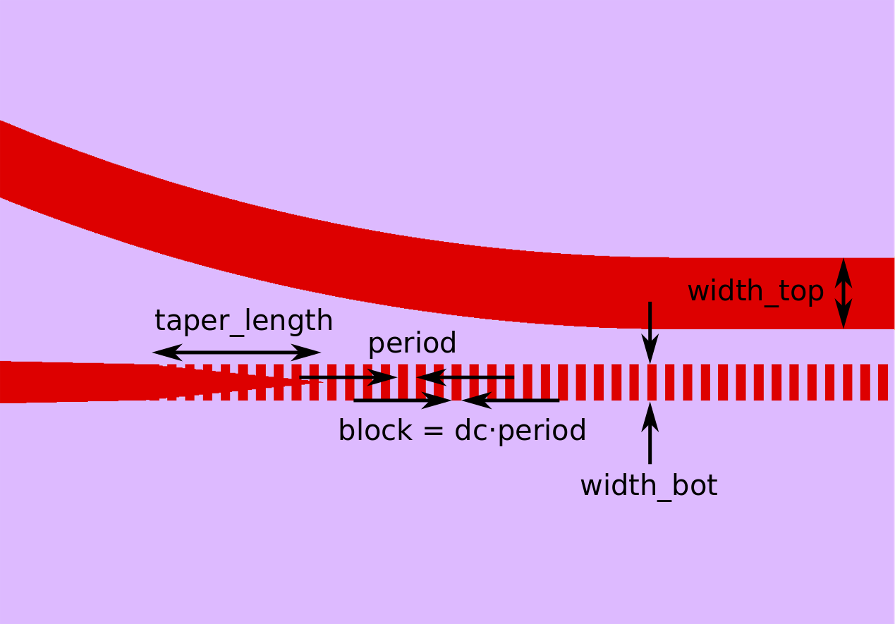
For more details on the principles and operation behind this type of component, please see https://doi.org/10.1364/OE.25.025310. This component uses one regular waveguide (at top) and one sub-wavelength grating (at bottom) to selectively reflect a certain spectral band to the input_bot port. Apodization of the top waveguide is also supported.
-
class
picwriter.components.SWGContraDirectionalCoupler(wgt, length, gap, period, dc, taper_length, w_phc_bot, top_angle=0.5235987755982988, width_top=None, width_bot=None, extra_swg_length=0.0, input_bot=False, apodization_top=False, apodization_far_dist=1.0, apodization_curv=None, fins=False, fin_size=(0.2, 0.05), contradc_wgt=None, port=(0, 0), direction=u'EAST')¶ SWG Contra-Directional Coupler Cell class.
- Args:
- wgt (WaveguideTemplate): WaveguideTemplate object
- length (float): Length of the coupling region.
- gap (float): Distance between the two waveguides.
- period (float): Period of the grating.
- dc (float): Duty cycle of the grating. Must be between 0 and 1.
- taper_length (float): Length of the taper region
- w_phc_bot (float): Width of the thin section of the bottom waveguide. w_phc_bot = 0 corresponds to disconnected periodic blocks.
- Keyword Args:
- top_angle (float): Angle in radians (between 0 and pi/2) at which the top waveguide bends towards the coupling region. Default=pi/6.
- width_top (float): Width of the top waveguide in the coupling region. Defaults to the WaveguideTemplate wg width.
- width_bot (float): Width of the bottom waveguide in the coupling region. Defaults to the WaveguideTemplate wg width.
- extra_swg_length (float): Extra length of SWG waveguide between coupling region and taper. Default=0.0.
- input_bot (boolean): If True, will make the default input the bottom waveguide (rather than the top). Default=`False`
- apodization_top (boolean): If True, will apodize the coupling_gap distance for the top waveguide using a Gaussian profile.
- apodization_far_dist (float): If apodization_top`=`True, then this parameter sets how far away the coupling gap starts. The minimum coupling gap is defined by gap. Defaults to 1um.
- apodization_curv (float): If apodization_top`=`True, then this parameter sets the curvature for the Gaussian apodization. Defaults to (10.0/length)**2.
- fins (boolean): If True, adds fins to the input/output waveguides. In this case a different template for the component must be specified. This feature is useful when performing electron-beam lithography and using different beam currents for fine features (helps to reduce stitching errors). Defaults to False
- fin_size ((x,y) Tuple): Specifies the x- and y-size of the fins. Defaults to 200 nm x 50 nm
- contradc_wgt (WaveguideTemplate): If fins above is True, a WaveguideTemplate (contradc_wgt) must be specified. This defines the layertype / datatype of the ContraDC (which will be separate from the input/output waveguides). Defaults to None
- port (tuple): Cartesian coordinate of the input port (AT TOP if input_bot=False, AT BOTTOM if input_bot=True). Defaults to (0,0).
- direction (string): Direction that the component will point towards, can be of type ‘NORTH’, ‘WEST’, ‘SOUTH’, ‘EAST’, OR an angle (float, in radians). Defaults to ‘EAST’.
- Members:
- portlist (dict): Dictionary with the relevant port information
- Portlist format:
- portlist[‘input_top’] = {‘port’: (x1,y1), ‘direction’: ‘dir1’}
- portlist[‘input_bot’] = {‘port’: (x2,y2), ‘direction’: ‘dir1’}
- portlist[‘output_top’] = {‘port’: (x3, y3), ‘direction’: ‘dir3’}
- portlist[‘output_bot’] = {‘port’: (x4, y4), ‘direction’: ‘dir4’}
Where in the above (x1,y1) (or (x2,y2) if input_bot=False) is the same as the input ‘port’, (x3, y3), and (x4, y4) are the two output port locations. Directions ‘dir1’, ‘dir2’, etc. are of type ‘NORTH’, ‘WEST’, ‘SOUTH’, ‘EAST’, or an angle in radians. ‘Direction’ points towards the waveguide that will connect to it.
Example Usage
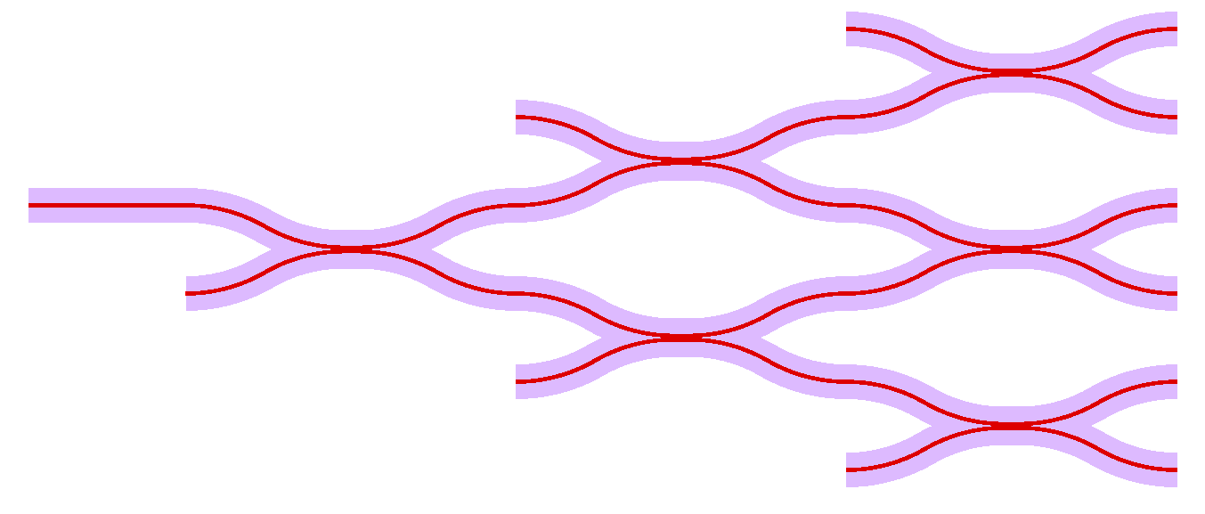
The directional coupler matrix shown above is generated by:
top = gdspy.Cell("top")
wgt = WaveguideTemplate(bend_radius=100, resist='+')

wg1=Waveguide([(0,0), (100,0)], wgt)
tk.add(top, wg1)

dc1 = DirectionalCoupler(wgt, 10.0, 0.5, angle=np.pi/6.0, parity=1, **wg1.portlist["output"])
dc2 = DirectionalCoupler(wgt, 10.0, 0.5, angle=np.pi/6.0, parity=-1, **dc1.portlist["output_top"])
dc3 = DirectionalCoupler(wgt, 10.0, 0.5, angle=np.pi/6.0, parity=1, **dc1.portlist["output_bot"])
dc4 = DirectionalCoupler(wgt, 10.0, 0.5, angle=np.pi/6.0, parity=1, **dc2.portlist["output_bot"])
dc5 = DirectionalCoupler(wgt, 10.0, 0.5, angle=np.pi/6.0, parity=-1, **dc2.portlist["output_top"])
dc6 = DirectionalCoupler(wgt, 10.0, 0.5, angle=np.pi/6.0, parity=1, **dc3.portlist["output_bot"])
tk.add(top, dc1)
tk.add(top, dc2)
tk.add(top, dc3)
tk.add(top, dc4)
tk.add(top, dc5)
tk.add(top, dc6)